Dirk Noy, Walters-Storyk Design Group (WSDG

Sound on Surfaces
When sound energy hits a surface we can observe one of three things or a combination thereof: The sound is geometrically re-directed (reflection), the sound is attenuated (absorption), or the sound is distributed more or less uniformly (diffusion) (see Figure 1) – this is assuming we disregard the sound partially traveling through the surface. These fundamental behaviors are very much connected – e.g. absorption can be understood as an “attenuated reflection” and diffusion is just a “redirected reflection”. So let’s look at these phenomena in more detail so you can join the discussion: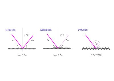 Figure 1: Reflection, Absorption, Diffusion
Reflection
Anybody out there ever played pool billiards? If you did – the concept of reflection certainly is not unknown to you. Just like a billiard ball bouncing off the cushion (and hardly losing any energy) the incident sound bounces off an acoustically reflective or “acoustically hard” surface. Whether this is a good thing or a bad thing does differ – targeted reflection of sound energy to the rear of a theater auditorium can be great – on the other hand – the focused reflections of a glass dome ceiling can profoundly cause an acoustical mess. Reflection in a control room environment can be used to redirect sound away from critical listening positions.
Absorption
Back to the pool table guys! Imagine the cushions being veeeery soft and chewy – the billiard ball hitting that surface would clearly deform the soft cushion and thereby significantly lose momentum. The same happens when sound hits an absorptive material: some part of the acoustical energy is transformed to other types of energy (mostly heat). Examples of acoustical absorbers are all sorts of porous foams or perforated / slotted surfaces. In both cases the underlying energy transformation mechanism is friction of air molecules. Absorption is useful to control unwanted reflections and consequentially to decrease excessive reverberation.
Absorption Coefficient
To characterize the properties of an absorbent material the absorption coefficient “alpha” was introduced. This coefficient describes the material’s conversion ratio of sound energy to other forms of energy as a normalized percentage (0% to 100%, or 0 to 1). Alpha varies with the incident sound’s frequency: Materials that have good absorption properties at low frequencies (alpha, for example, over 60%), often have little or no absorption at high frequencies (for example, less than 20%) and vice versa. 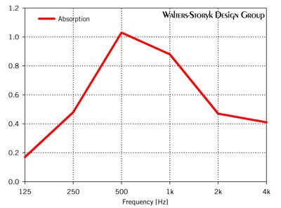
Figure 2: Absorption Coefficient of a Slotted Wood Material
One of the tasks for the acoustical designer is to find a weighted compilation of the “right” absorber materials for a given acoustic situation. On a side note – sometimes one can find absorption coefficients greater than 100% (or greater than 1). Although this might look like a mistake this is caused by additional participation of the material edges (and sometimes backside) of the absorber when measuring in a reverberation chamber.
Absorptive materials are available in dozens of designs, shapes, colors, formats, etc. – a current summary would encompass e.g. plastic, perforated or slotted wood panels, metal in various shapes, fabric, foam, various wall and ceiling plasters, microperforated foil, transparent laser cut panels etc. and any combinations of the above. A selection is made according to the acoustical properties, the desired aesthetics and integration solution and the available budget.
Please note that more expensive materials do not necessarily have better acoustical properties – high priced materials sometimes just offer specific aesthetics or a particular new functionality which will then justify the larger price tag. Sometimes though you’re just funding the manufacturer’s advertising budget – so keep your eyes (eh – ears I guess) open…
Low-frequency absorption
Low frequency control is a main problem in small acoustic spaces due to the wavelengths of these frequencies being similar to the room’s dimensions. Membrane absorbers and Helmholtz resonators are absorber designs suitable for frequencies below about 125Hz.
A membrane absorber is a moveable rubber, wood or metal membrane mounted in a frame. At certain frequencies (or, depending on the type: below a certain cut-off frequency), the membrane starts to vibrate when exposed to sound pressure – thus transforms energy from the sound field to heat. Helmholtz resonators work like a coke bottle that can be used as a whistle: A given closed volume (the volume of the bottle) has an opening with a particular length (length of the bottle neck) and a particular cross-section (diameter of the bottle neck). Helmholtz resonators are easily incorporated in a space where otherwise unused volumes are available (e.g. a raised platform cavity in a home theater, or a void above a suspended ceiling).
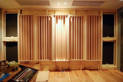 Figure 3: Left and Right Edges: Exposed Membrane Resonators for Low Frequency Absorption. Center: QRD Diffractal (Courtesy of Sunshine Mastering, Vienna)
Figure 4: Same Wall – After Installation of the Acoustically Transparent Fabric (Courtesy of Sunshine Mastering, Vienna)
Diffusion
Diffusion is used to uniformly distribute sound in space. Diffusors are available in a range of shapes and sizes. Where the size determines the frequency range that is diffused by the device, the shape will characterize the degree of distribution in space: a fully hemispherical distribution at all frequencies is desirable, but hard to achieve. At the moment there are two metrics to measure and characterize scattering surfaces – the Diffusion Coefficient d, and the Scattering Coefficient s, both frequency dependent.
A commonly used approach is the so called QRD Diffusor, or quadratic residue sequence Diffusor. The device’s geometry is based on a prime number which determines the length after which the sequence repeats periodically and thus also the number of wells the diffusor consists of. Typically one of the prime numbers 7, 11 or 13 is used. One dimensional diffusors contain depth variation in one dimension, thus forming linear divided wells or steps of varying depth, whereas two-dimensional diffusors offer depth variation in two perpendicular directions, thus forming a lattice of divided cells or steps of varying depth – looking a bit like a skyscraper skyline.
Diffusion can be used to control reflections when the placement of further absorption is not desired (e.g. when the reverberation times already are on the low side).
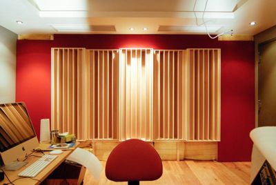
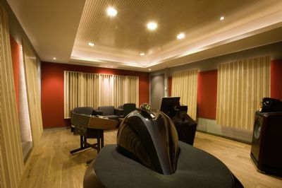 Figure 5: Finished Mastering Room – Rear and Side Wall Diffusors, Ceiling and Wall Absorbers (Courtesy of Sunshine Mastering, Vienna)
Putting It All Together
After the design of the shell – the wall structures of the facility, including solving the sound isolation issues – a large amount of design time is spent on the complex issue of balancing reflection, absorption and diffusion in a room. Besides finding the optimal acoustical solution these are surfaces that are actually exposed to the eye – and so a pleasing aesthetics is asked for as well.
To preview and study the acoustics of a space pre-construction a number of tools are available. Some of these, plus the equipping of the space with loudspeakers and a calibration system will be touched upon in the next and last article of the series.
Read next Resolution article, on acoustical Simulations, electroacoustics and audio monitoring systems.

