by Dirk Noy, Walters-Storyk Design Group (WSDG)
![]()
Maybe you remember – we’re still busy planning and building our dream media production facility – the basic issues of site selection and layout considerations were covered in the last article of this series. Today’s hot topic is defining and achieving appropriate sound isolation between the facility’s rooms as well as sound isolation to and from the neighbors.
What Is Quiet?
Aha – interesting question. In a regular residential or office environment, sound pressure levels of 30 to 40dB(A) or even higher are constantly present – “quiet” would be considered anything that is approximately in or below that sound pressure level range – for it means that we can’t hear much of the fax machine while the copier and the coffee machine are running anyway. For media production facilities “quietness” is a far less forgiving term. We firstly sometimes have to record sounds or have to mix a section of a soundtrack that are particularly very low in level, and additionally we deal with microphones instead of human ears – with proper preamplification, gain structure and processing these can be even more sensitive.
For defining quietness levels in recording studios and critical listening environments the use of the dB(A) scale is not sufficiently accurate. A number of appropriate international standards are in place, e.g. the Noise Criteria (NC), Noise Rating (NR) or Grenz Kurve (GK) values. The IRT (Institut für Rundfunktechnik) uses a combination of NR and GK curves as shown in Figure 1 for production facility use. Recommended values for various room types are indicated in Figure 2 – the mentioned curve should not be exceeded at all frequencies.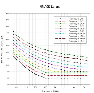
Figure 1: IRT Noise Level Chart For Recording And Mixing Environments
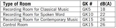
Figure 2: IRT Permissible GK Values For Various Room Types
What Sound Isolation Do I Need?
Sound isolation requirements are a function of the required quietness of a particular space and the potential noisiness of the surrounding areas. For every room two parameters therefore have to be defined either by an educated assumption or – preferrable, but not always possible – by an acoustical measurement: on one hand, the maximum potential sound pressure level, and on the other hand the required quietness of the area in question. These two values can be indicated for every room on the facility floorplan – the level difference between adjacent spaces then defines the required sound isolation – highest sound isolation is required between the potentially loudest spaces and the rooms with the lowest permissible sound levels.
Sound isolation is a complex term that varies widely over frequency for any construction material. For easier communication and comparison a procedure has been developed to translate a series of transmission loss values over a limited frequency range (125Hz – 4kHz) into a one-number STC (Sound Transmission Class) figure using a standardized contour curve. I will spare you the details here – but be advised that a “STC49” sound isolation door will not provide 49dB of isolation at 60Hz (but significantly less). On the other hand, it will provide approximately 49dB of isolation at 500Hz, and more at higher frequencies. To make matters worse, a STC47 door could potentially be better at low frequency isolation than the STC49 door… For real purchasing decisions it is wise to look at the data sheet carefully – nevertheless, STC is a popular and useful measure.
A sample facility’s sound isolation requirement sketch can be found in Figure 3 – showing assumed maximum sound pressure levels and quietness requirements for the various rooms. This information is then used to design the appropriate wall construction. The shown facility requires three different partition types A, B and C; A being the most complex one – directly dividing the potentially loudest rooms (highest sound pressure level number) from the ones that need the most quietness (lowest GK number). 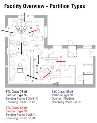
Figure 3: Facility Overview – Sound Isolation Requirements and Partition Types
Defining the specifications for sound isolation has to be done carefully – it substantially impacts financial implications: more sound isolation means higher cost in design and construction. On the other hand – one doesn’t want to end up with a facility where the required simultaneousity cannot be offered. In terms of construction budget, the easiest way to properly isolate two rooms with high STC requirements is to position the two rooms far apart from each other – which is not always feasible.
Achieving Sound Isolation
Sound travels over two different paths. Airborne sound is carried through the air (sic!). Blocking airborne sound is achieved by inserting a solid material (such as a brick or gypsum wall). Structure borne sound is carried by the structure itself. Blocking structure borne sound is achieved by inserting a soft material (such as rubber or air). For airborne sound can transform to structure borne sound and vice versa both travel paths need to be blocked. A smart combination of solid material (“mass”) and soft material (“decoupling”) therefore needs to be used. In more sophisticated terms, materials with varying acoustical impedances must be combined not unlike a layered sandwich.
Building for Sound Isolation
The combination of mass and decoupling in construction consequentially leads to so-called room-within-room construction, where every room is a closed container with an individually decoupled (or “floating”) floor, and each with individually decoupled walls and ceilings. For we still haven’t figured out how to float floors without any support at all the floating floor is built as a separate layer, decoupled from the existing floor by an arrangement of springs. The spring in its simplest incarnation is a rubber or elastomer element – more complex types are steel springs or even air springs which offer the highest isolation even at very low frequencies.
The walls are constructed on top of the floating floor – basically freestanding and without rigid support to either the existing walls or other acoustical walls. For the walls need some sort of fixation to prevent toppling a series of decoupling bracing devices has been developed by various manufacturers. The ceiling is then either mounted on top of the wall construction, or built as a spring-suspended and therefore decoupled ceiling.
As mentioned in the last article, relatively simple two wall systems with floating floors and suspended ceilings can achieve a STC sound isolation value of about 60..70dB. This is fine for e.g. a control room > iso booth wall, but not sufficient for two adjacent, independently operated post production rooms – meaning that more complex systems need to be employed. 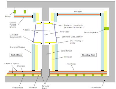
Figure 4: Sample Partition Types
What Does Not Work?
A common and still popular misconception is that materials such as pyramid shaped foam elements or even egg cartons increase sound isolation – I am sorry to tell you that that is not the case. There is no shortcut to be found for real sound isolation – we will need to go for the full monty, meaning full decoupling and room-within-room construction, using acoustical doors and windows. This is bad enough news for media production facilities – it is even worse news for large spaces such as clubs or film theaters, so consider yourself to be lucky when you’re “only” dealing with a studio…
And there’s more news for you – the hits just keep on coming… please keep in mind that when we’re done building our sound isolated container we have not yet done a single thing for the room acoustics – meaning that we’ve probably built a well-isolated but yet completely useless echo chamber. Be on the lookout for the next article in this series, for there we will deal with the interior dressing of the room, taking account fancy things such as absorbers and diffusors.
Read next Resolution article on room acoustics, absorption and diffusion.