by Dirk Noy, Walters-Storyk Design Group (WSDG)

Acoustical Simulations
Only a few years back, detailed acoustical simulations and auralizations could only be performed either by playing with large architectural scale models, using tiny sound sources and equally tiny receiver microphones or by utilizing ultraexpensive mainframe style academic grade supercomputers. The digital revolution has brought this technology to desktop size and economics; commercial acoustical simulation software nowadays runs on standard MS Windows based PCs with no additional hardware requirements.
The Process
Performing meaningful acoustical simulations is a three step procedure. In step one, the space needs to be translated from architectural information (such as drawings and measured dimensions) to a so-called “model” – the model is a three-dimensional representation of architecture in the digital domain. In step two, the model will be dressed up with acoustical surfaces. Basically, every surface of the model (usually walls, floor, ceiling, but also furniture, curtains, installed acoustical materials etc.) needs to be assigned specific acoustical properties.
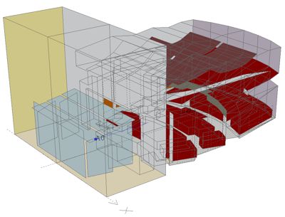 Figure 1: Acoustical Simulation Model of a Theater. The colors indicate acoustical surface properties. (Gabriel Hauser, WSDG, using CATT-Acoustic simulation software”)
Step three is the fun part. In this step, the user can perform virtual acoustical measurements in the model and learn from the virtual measurement results. One example would be the study of decay of sound in a recording space. Another example would be the study of speech intelligibility in an airport terminal. And yet another example would be the frequency response of the First Violin at the Conductor’s lectern. Or at the oboist’s position. Or in the hallway. As with any experiments, the test results offer answers to specifically asked questions; therefore the test setups (“questions”) will need to be driven by the nature of the task. The results of these tests are presented in a diagram format. Decisions can be taken to go back to step one or two and modify some architectural parameters or acoustical surfaces to hopefully obtain better acoustical results.
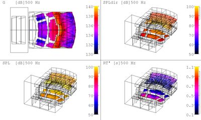 Figure 2: Sample Simulation Results. Top right: Direct Sound Pressure Level Distribution; Bottom right: Reverberation Time Distribution. All at 500Hz. (Gabriel Hauser, WSDG, using CATT-Acoustic simulation software)
Acoustical Simulations for Small Spaces and Low Frequencies
Regular acoustical simulations are a valuable tool, but offer no information in the low frequency octaves due to their inherent ray-trace algorithms. Lately, new tools have become available to allow acoustical studies at low frequencies. These tools are based on the so called „Boundary-Element-Method“ or BEM (related to the „Finite-Element-Method“ FEM) and allow numerical solving of the wave equation at predetermined discretized planes. This applies to room acoustics, for the listening planes are known. The process requires substantial computational power (basically a numerical solving of the wave equation for every single lattice point in the predetermined plane to be considered). The results allow specification of appropriate low frequency absorbers.
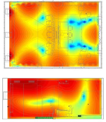 Figure 3: Sample BEM Simulation Result. Top: Listening plane view (height = 1.20m) at 60Hz; Bottom: Section view (center plane) at 60Hz. (Carlo Fickler, WSDG, using ABEC simulation software)
Positioning the Audio Monitors
Acoustical simulations are helpful to determine specification and location of absorbers and diffusors but they also do assist in evaluating loudspeaker positions and finding optimal solutions. Common audio monitors display an omnidirectional radiation pattern below a certain frequency, typically e.g. below 120Hz. Hence at low frequencies a listener in a room will most definitely hear the direct sound, but also a number of reflections from the surrounding walls – this effect is called Speaker Boundary Inteference or SBIR. To eliminate these effects audio monitors are often soffit mounted directly into the wall. Alternatively they can be positioned either very close to adjoining surfaces (so the reflections are practically in phase with the direct sound) or very far away from adjoining surfaces (so the reflections are significantly lower in level and later in time). Additionally, for a correct stereo representation, the left and right audio monitors must be equal distance from each other and from the listener position, respectively.
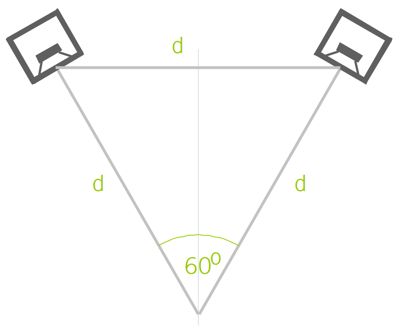 Figure 4: Audio Monitor Geometry for Stereo Systems
System Calibration – Phase
Medium and large scale audio monitors may offer adjustment in the time domain, which are the phase relationships between the individual low, mid and high frequency drivers. The goal is to compensate for differences in time-of-flight from these drivers to the listener positions such that a fully coherent wavefront arrives at the listener’s position. In fact these are very small differences but it is astonishing how much a correct phase setting contributes to a pristine, clear, well-staged and transparent sound. Correct phase or delay settings are found by measuring the individual drivers’ Impulse Responses, evaluating the respective time-of-flight and properly delaying the drivers closest to the listener’s position. An Impulse Response measurement of the entire system should then result in a single-peak graph as shown in Figure 5.
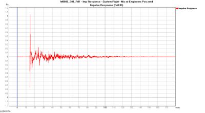 Figure 5: Impulse Response Measurement
System Calibration – Equalisation
Many audio monitors offer some crude on-board adjustments in the frequency domain. This is helpful, but more often than not a dedicated analog or digital outboard parametric equaliser or loudspeaker processor will be employed. The goal is to obtain a linear reproduction throughout the audio spectrum. Generally, reducing energy is preferrable over adding energy. Parametric equalisers offer the ability to precisely tailor the correction suited for a particular problematic frequency range.
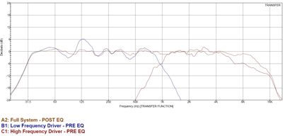 Figure 6: Frequency Response Measurement of a Two Way Active Audio Monitor System
System Calibration – Listening Test – The End
When the measurement results are satisfactory, the last and utterly critical step in the System Calibration process is the listening test. I carry a carefully selected bunch of reference CDs and .wav files on my iPhone with me for this final step. Sitting down in the engineer’s position, listening to the audio system and the room for half an hour I will always suggest some further minor modifications to get the top-notch reproduction quality we worked so hard for to obtain. This of course is a deeply satisfying moment – and also the last day of the project’s design, construction and installation – which again is the first day of a meaningful, enriching and hopefully successful life for the facility and its owners.

